top of page
Keyshot Rendering/Animation

End to End Project Management

BOM & Part Costings
Skills in this Project:
Solidworks

Plastic Injection Moulding
Photoshop/Illustrator

Rapid Prototyping

DFM & DFA Optimisation
Optimising For Manufacture & Assembly
The Overall Project:
This was a project that I led at Evolve Group, where our client came to us with a previous design that needed to be optimised for injection moulding in Australia. The aim for the client was to have the parts ready to be tooled, reduce part costs, improve ease of assembly, and optimise material selection for the context of use.

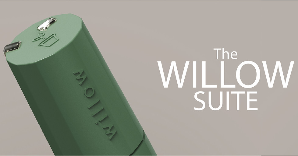
What is it?
The'Willow' is a successfully crowd-funded product that is a compact system that measures moisture and humidity/temperature for indoor/outdoor house plants. The soil sensor offers light pipes on the exterior that will alert the user when the plant needs to be looked at. The app allows the user to find additional information on what the plant needs. Multiple sensors can be used, which can all be synced to the 'Gateway Base'. The probe can also be extended to fit into larger-sized pots.


The Material Selection:
The material was optimised for the context of use but also to save in part costs for the client. The client also wanted the option to over-mould steel probes into the product. PP AP3AW was chosen as it is easy to source material that is cost-effective compared to other resins. PP has the ability to be used in over-moulding and has lower shrinkage coming out of the tool, which can help with part tolerances. Mouldable silicone was chosen for the light pipes as it can achieve optical clearness but also has enough flexibility to be able to be press fit into the housing during assembly.

The Final Prototype:
From the client signing off on the technical drawings, we proceeded with a 1:1 professional prototype that offers near identical material surface finishes, tolerances and materials to a production model. This was done by an external supplier via the process of CNC for the plastic parts and vacuum castings for the light pipes.
The Technical Drawings:
Below is a sample of the technical drawings provided to the client to sign off the design to proceed with the final prototype. Once the prototype is signed off, we would proceed to quote for tool manufacturing.
What I Learnt:
This project challenged me to learn more about injection moulding procedures while also being able to take an already-designed product to be optimised for plastic production. I learnt more about material selection and moulding procedures to what would be cost-effective on a budget. I also learnt more about communicating with external stakeholders in tooling/part pricing for injection moulding and communicating with external prototype suppliers for their recommended materials for light pipes. At the time of writing, this project is being tooled in China for the initial 30,000 units to be manufactured in China before the tool is exported to Australia to being its next manufacturing run.

Light Pipe Assembly:
Two separate light pipes are used in the assembly. One to let the light into the humidity sensor and the other for the LED light (to signal information to the user). The LED light pipe was designed to surround the LED to be more effective in transmitting the light. The sensor light pipe was simplified to sit over the sensor and have a frosted surface finish to better diffuse the light.
Assembled Internals:
The client requested a few different changes from the original design to better hold the coin battery into position while also reducing the number of o-rings to reduce costs and labour involved during assembly. So the new positions for the o-rings had to be in optimal positions to ensure no water intrudes into the system.


Achieving the IP53 rating:
Using the moldable silicon with the O-Rings, the product can achieve the IP53 rating as the creates a water-tight seal. The light pipes were designed to have lips that will overlap once pushed into place.


Other Images of the Soil Sensor:
What Needed to be Changed:
Upon the first review, the Soil Sensor required changes to be DFM & DFA optimised. The changes are:
1. The light pipes were originally acrylic material that would be over-moulded with the top housing. Over moulding process would be too difficult and costly to achieve due to the complexity of the parts. Acrylic material won't give you an optically clear part, either.
2. Tolerenacing of the parts would need to be increased to accommodate material shrinkage after the parts have cycled in the tool.
3. Improve how the steel holds the small steel probes during over-moulding.
4. include more guide ribs to improve the assembly process, so the assemblers know when the parts are put together correctly.
5. More ribes to old in the PCB/Coin Battery in place to prevent it from moving.

The Gateway Base:
The Gateway Base was another part that needed optimisation from the previous design to be ready for tooling. These changes are:
1. Improve the assembly of the upper & lower parts. This is by modifying the pin bosses to be stronger and be easier to locate for the assembler as previous ones were near impossible to achieve.
2. Improve the assembly of the PCB with a USB-C connection to the part. Previous design the PCB wouldn't fit.
USB-C Placement:
Gateway Based modified to split where the USB-C input is so that it is able to be assembled. While having this feature it makes that the upper&lower parts can only be assembled one way causing no confusion for the assemblers.


Internal Pin Bosses:
The pin boss was modified for the easier assembly process and to improve the strength of the feature. As the previous version snapped too easily when assembling both parts
PCB Fitment:
Ribs around the circumference of the PCB were added to secure the PCB in place when assembling. On the show face of the ribs would have an interference/sheer fit with the upper part internal face holding the 2 parts together.


Other Images of the Gateway Base:


bottom of page