top of page
Continued Design Work on This Project:
After the completion of this project, further work was done on getting the design to the design more compact and developed internals to be more functional. Furthermore, being inspired by the Apple design philosophy. While also exploring new techniques in Keyshot rendering, Video Editing. To see more about this project, click on the image to the side.

Sketching to ideate where the screw bosses could be located within the design

Skills in this Project:
Solidworks/Rendering

DFMA

Arduino
Photoshop/Illustrator

3D Printing

Prototyping

Designing For Manufacture
The Overall Project:
This was an individual project that lasted 7 weeks, where I was introduced into designing for manufacture. This task by designing a phone dock, educated us in the notion of injection moulding, where we would learn the ins and outs of being able to CAD model a design that could be injection modelled. I really enjoyed the development side of the project, being able to teach myself to think about the manufacturing side of Industrial Design.

What is it?
The 'Sky Guy' is a phone dock that was inspired by the Millennium Falcon from Star Wars. It was designed to be injection moulded where the intention for it was to be mass-produced. The design also suited the purpose of being able to charge the phone, while also offering Bluetooth connectivity to transfer information from the phone to the dock, which will be displayed on the OLED screen.
Features:

Phone Charging
OLED Display
Bluetooth Connectivity
Phone Stand


The OLED Display:
The design offers an OLED display at the front of the dock which offers the ability to display data that includes time, date, battery percentage, and other information the user can program into the system. This data is gathered from the user's phone as the dock includes a Bluetooth module internally.
Docking a Smartphone:
The design allows the user to slide in their smartphone at an angle for it to dock and charge. The dock offers a high backing so the phone is held in with support so won't damage the input connection when it moves. This can be from if the user accidentally bumps into it.
The Design Process
The Research:
Apart from researching standards within Injection Moulding plastics. I gathered design inspiration from the Millennium Falcon in terms of its colour aesthetics and cockpit form for the phone dock.

The Development:
In developing the idea further, I sketched out the idea with the concept of creating a design that allows for more streamlined construction for the end-user. While being able to prepare the design to be injection moulded. The photos below illustrates the process of how the pouches can be constructed.


Sketching into the assembly/disassembly of the design. While also ideating to what parts could be involved and the related screws/screw bosses for injection moulding
The Prototyping:
From the initial sketches, I CAD modeled each part individually, for them to assemble to one part. I designed the phone dock to be large enough so it could be able to nicely fit an iPhone 6s (which was my phone at the time). The design was also based around fitting an LCD screen, an Arduino UNO R3, and a Bluetooth Module.
Prototyping the sizing and form of the design from a 3D print

Prototyping how a smartphone would fit into the design
Injection Moulding Analysis:
Analysis of the parts was conducted after the CAD model was completed to showcase that the parts could be injection molded. The Illustrations below showcase what kind of tests were done on each part


Undercut Analysis of top part
Flow Analysis of the top part

Draft Analysis of top part
The Final Design:
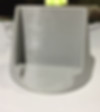
The final design of the phone dock was 3D printed, as it was the only solution that was available that could give similar results to injection moulding. The model showcased how a phone and the electronics would fit in as seen in the pictures below.
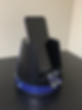


Final model with phone attatched
Final model without phone inserted
How the electronics fitted internally
How The Design Comes Together:
For designing for manufacturing, the product is comprised of snap hooks and screw bosses that allow the design to be assembled in 5 parts. These 5 parts were designed to be optimized for injection moulding with 1-3 gate locations required. The internal technologies are mainly located on the base part so they can be easily accessible around the product, but also, the base part had a large enough diameter to fir the Arduino UNO R3. The exploded view below depicts the assembly of the parts required for the design.

Technical Drawings:
Technical Drawings were developed as part of learning how to supply the manufacture with enough information for them to mould your product.

Top Part Drawing

Bottom Part Drawing
What I Learnt: I was really passionate about this project through how it solely relied on research and development for the design to succeed, from CAD prototyping to proposing new ways in getting the phone dock compatible for injection molded. I learned new skills in using Solidworks and a new level of attention to detail.
bottom of page